JGJimmy Grozav

MECHANICAL ENGINEERING PORTFOLIO

From an idea
to working hardware.

I'm Jimmy, a mechanical engineering student who designs, builds, and tests mechanical and electromechanical systems.

Explore my projects

SELECTED WORK

01 — 03
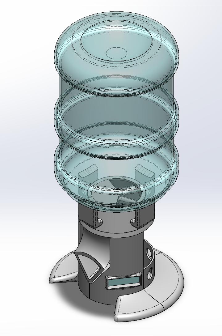
SolidWorks assembly model of the automated dog feeder, showing the hopper and dispensing mechanismSolidWorks assembly

01 / 03 · ELECTROMECHANICAL DESIGN · 2026

Automated
Dog Feeder

A working dispensing system that combines custom FDM-printed parts, off-the-shelf hardware, motor control, and tray-position feedback.

10completed functional test cycles
~1.5 cupsdispensed per feeding
SolidWorksFDM prototypingRaspberry Pi Pico 2 W
Watch the feeder demonstration ↗Captions available on YouTube.

The challenge

Develop a remotely operated feeder with scheduled dispensing, while integrating the mechanism, electronics, and a practical assembly.

My contribution

Designed and fabricated the mechanism, selected hardware, integrated the controller and sensors, and assembled the prototype circuit board.

What testing changed

Added an anti-rotation tab to support gearbox reaction torque, Hall-effect tray feedback, and improved fastener access. Further refinements identified include food flow and hopper stability.

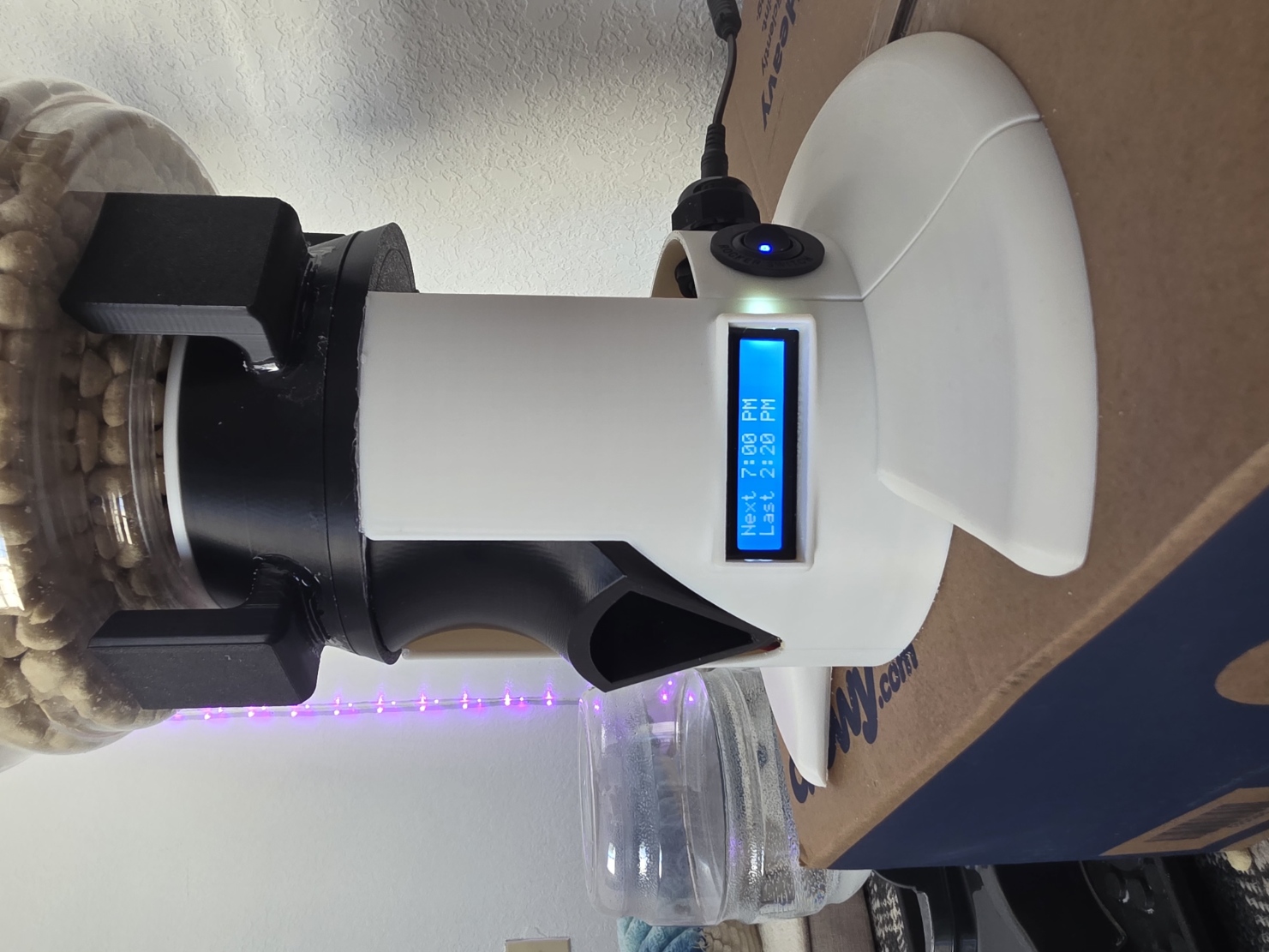
Final assembled dog feeder with food hopper, dispensing chute, white printed enclosure, and illuminated feeding schedule display
Final prototype · From an idea to working hardware
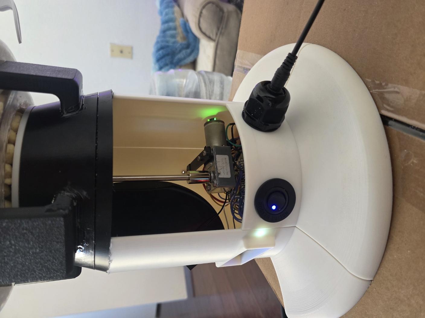
Interior of feeder showing gearbox, controller, wiring, and mechanical supports
Inside the assembly · Mechanical and electrical integration

BUILD. TEST. UNDERSTAND.

Making the invisible visible.

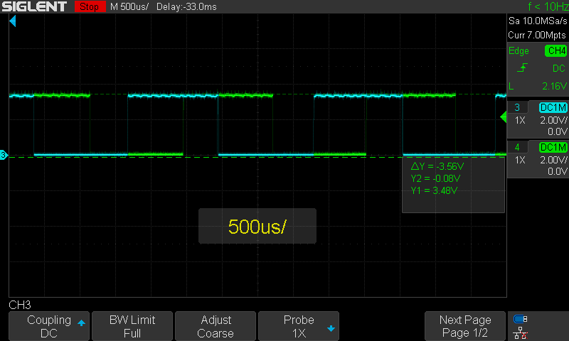
When the software gave confusing readings about the motor’s direction, I used an oscilloscope to see the electrical pulses from its motion sensor. These two traces helped me check what the motor was telling the controller.

That investigation helped shape the final design: a magnetic sensor locates the tray, while the motor’s sensor checks for movement.

Two colored traces showing electrical pulses from the motor’s motion sensor
Motor feedback, made visible · Select the image to enlarge.

02 / 03 · ANALYSIS & EXPERIMENTAL VALIDATION

Cantilever Beam
Structural Validation

Compared analytical predictions, linear static FEA, and physical testing of FDM-printed PLA beams to investigate failure loads and stiffness.

ANSYS MechanicalMATLABHand calculations

FAILURE LOAD · BEST-MATCHING SPECIMEN

Analytical prediction15.69 lbf
Measured failure15.55 lbf

Less than 1% difference in failure load for this specimen. Stiffness showed larger discrepancies.

Analytical foundation

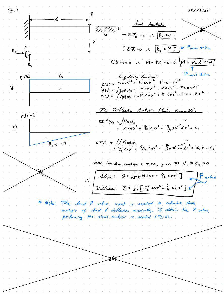
Derived bending and deflection equations using Macaulay’s singularity functions and implemented predictions in MATLAB.

Manufacturing matters

Used effective isotropic properties as a simplifying approximation while considering FDM anisotropy and orientation-dependent strength.

Learning from disagreement

Examined material assumptions and fixture compliance to investigate stiffness discrepancies. A close failure-load result does not establish accuracy for every response.

FROM THE PROJECT REPORT

The model.
The material.
The measurement.

Follow the cantilever study from analytical predictions to physical evidence.

Engineering notebook

Hand calculations

Handwritten free-body diagram, shear and moment diagrams, and singularity-function derivation of beam slope and deflection

Free-body analysis, shear and moment diagrams, and a singularity-function derivation establish the analytical foundation before numerical modeling.

Source: Cantilever Beam Bending Stress Validation Report · p. 19
01 / MATLAB

Analytical model

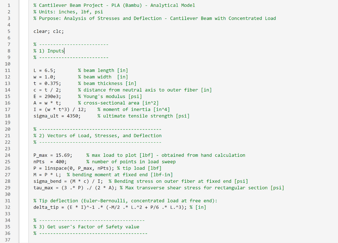
MATLAB Live Script with beam geometry, material properties, and load-dependent stress and deflection calculations

The Live Script evaluates beam behavior across a range of loads using the specified geometry and effective material properties.

Source: Cantilever Beam Bending Stress Validation Report · p. 23
02 / ANSYS FEA

Numerical prediction

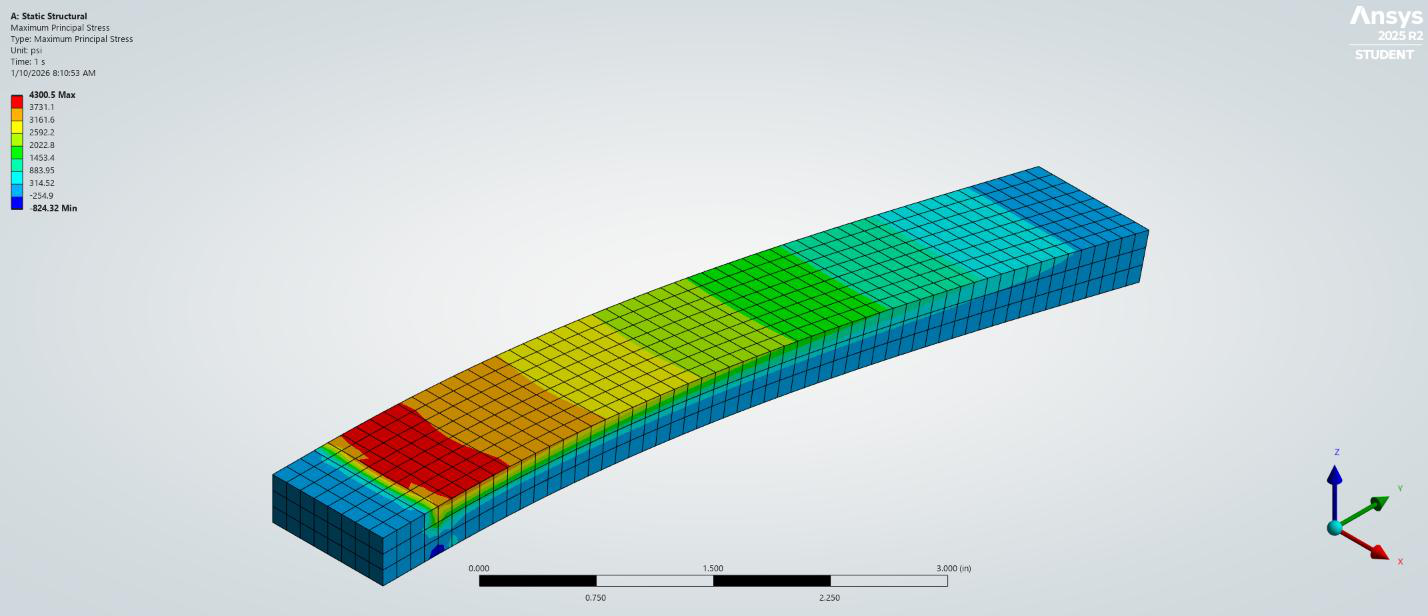
ANSYS maximum principal stress contour for the cantilever beam

Maximum principal stress visualization from the report’s linear static analysis. The modeled response is compared with physical evidence.

Source: Cantilever Beam Bending Stress Validation Report · p. 5
03 / FDM specimens

Physical evidence

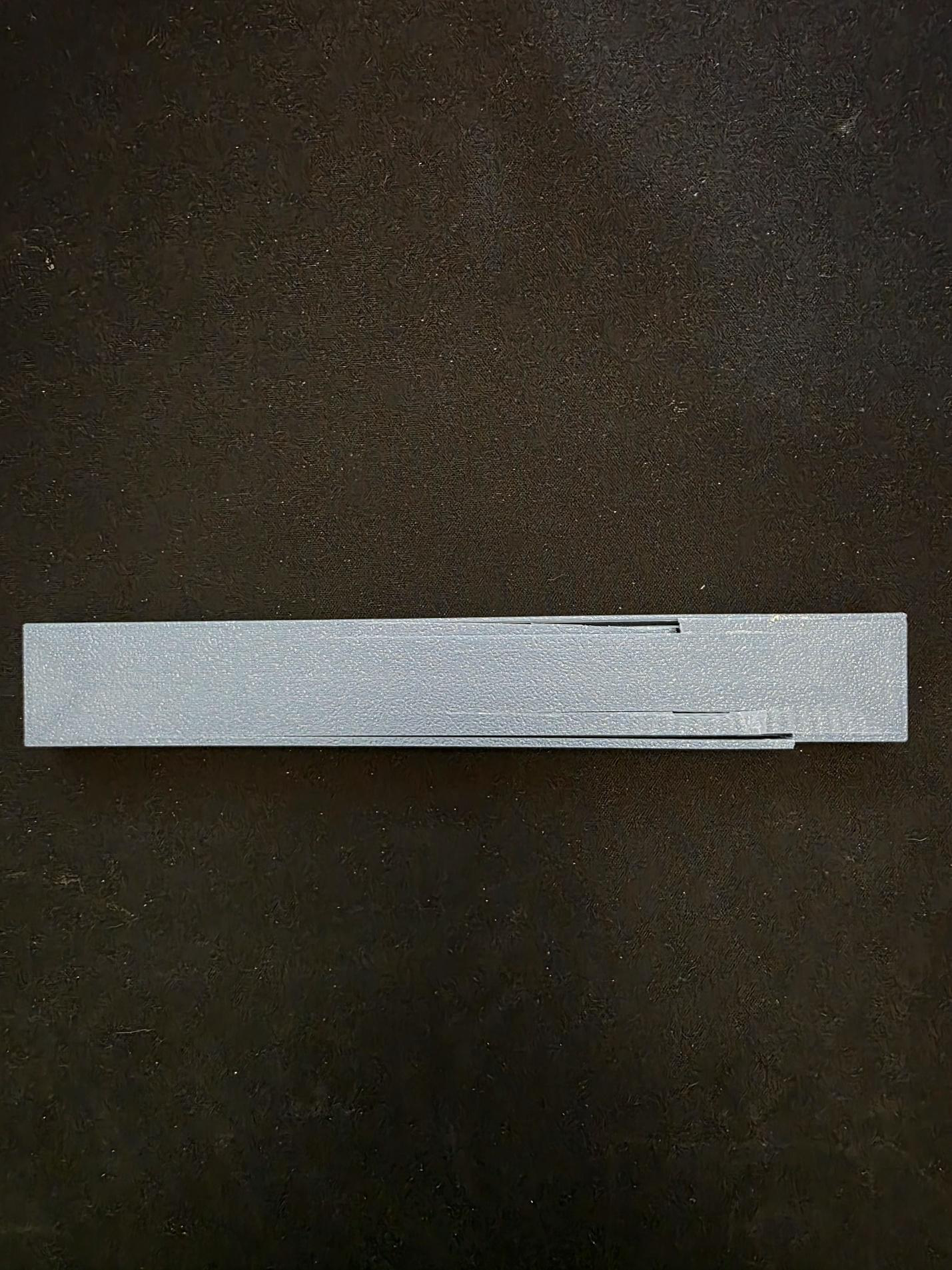
Top view of a printed PLA beam specimen showing damage after testing

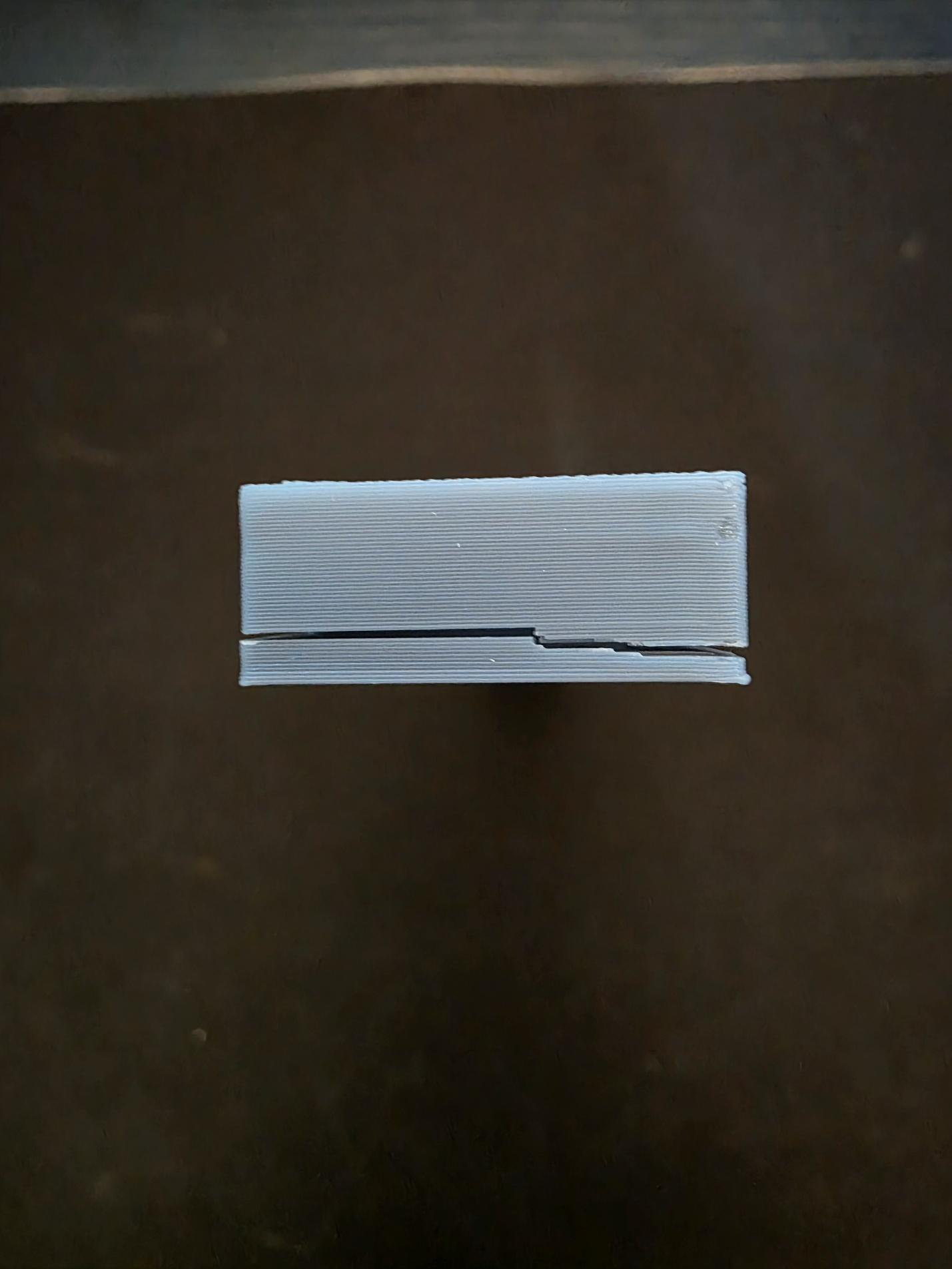
Post-test specimen photographs document the printed beam’s condition. End-view evidence provides a closer look at the printed layers.

Source: Cantilever Beam Bending Stress Validation Report · p. 9End view of the tested PLA specimen showing separated printed layersInspect the specimen end view ↗Report · p. 16
04 / Digital force gauge

Measured response

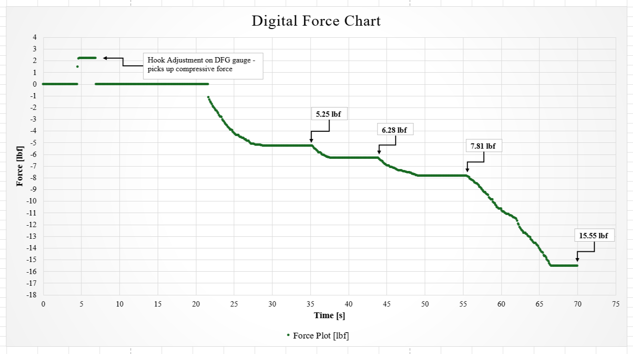
Digital force versus time chart annotated at 5.25, 6.28, 7.81, and 15.55 pounds force

Recorded force data captures the loading sequence and pauses for deflection readings. The negative sign reflects the instrument’s force direction convention.

Source: Cantilever Beam Bending Stress Validation Report · p. 29
03 / 03

PRACTICAL DESIGN · 2024

Clutch Alignment Tool

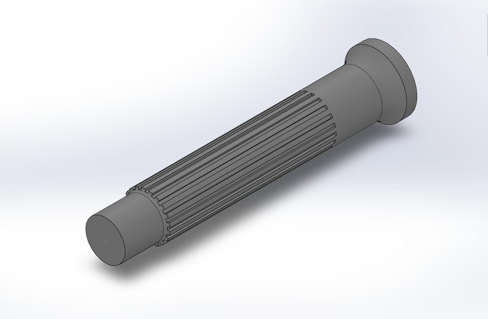
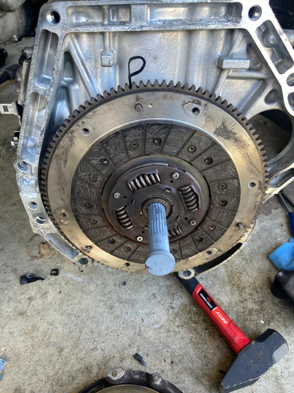
Designed and FDM-printed a clutch alignment tool in SolidWorks for a 2007 Honda Civic. Verified its fit through successful transmission installation without alignment-related rework.

SolidWorksFit & alignmentFunctional testing

ABOUT ME

Engineering grounded in hands-on work.

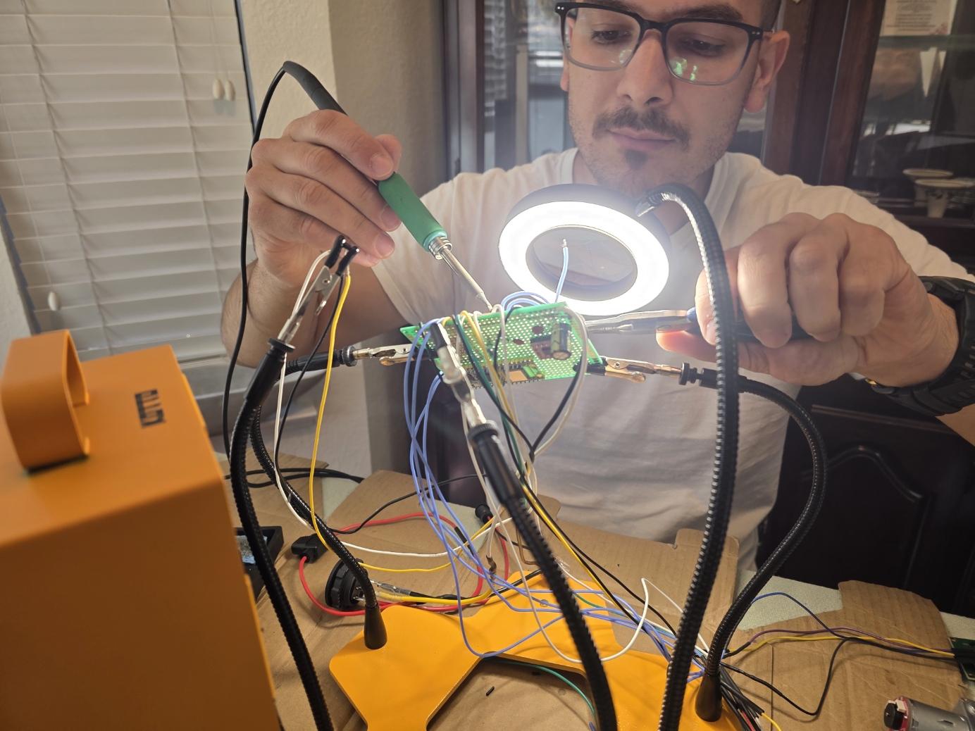
Jimmy Grozav soldering the prototype circuit board for his automated dog feeder
Assembling the feeder’s prototype circuit board.

I study mechanical engineering at California State University, Sacramento, with interests in mechanical design, structural analysis, and thermal-fluid systems.

Since September 2026, I have been a Formula SAE member with Hornet Racing at Sacramento State, working with the team to build the frame. My independent automotive work has developed my approach to diagnosing faults, testing explanations, and verifying repairs.

As a Deaf engineering student and Deaf interpreter, I value clear documentation, accessible technical discussions, and thoughtful communication.

Education

BS Mechanical Engineering
California State University, Sacramento
Expected Spring 2028

AS Electrical Engineering
American River College
2021

Involvement

Formula SAE · Hornet Racing
Frame subsystem
September 2026–present

Tau Beta Pi
Engineering honor society

ASME
Associate Member

Technical toolkit

  • SolidWorks
  • ANSYS Mechanical Linear static FEA
  • MATLAB & Simulink
  • FDM printing
  • Sensor and motor integration

CONTACT

Let’s connect.